During NVH performance development and quality control for pickup trucks, cabin ear pressure is one of the core pain points affecting ride comfort. Its root cause is closely related to the vibration coupling characteristics of the powertrain, chassis suspension and body connecting structures. As a major vibration source and noise-radiating component of the complete vehicle, the exhaust system uses hangers as critical force-transmitting joints connecting the exhaust system to the frame. These hangers serve multiple functions including vibration isolation, position limiting and load transfer. The mounting location and structural stiffness of hangers directly determine the vibration isolation performance when exhaust vibration transfers to the vehicle body.
一
Problem Description and Diagnosis
For a pickup truck equipped with a 2.0T inline four-cylinder diesel engine, the subjective noise evaluation at the rear cabin is unacceptable under the ACOFF idle condition when the engine speed is 850 r/min (2nd-order frequency at 28 Hz). Objective measurements were carried out using the ATOM Analyzer software, and the results are shown in the figure below: the rear cabin noise at 28 Hz is 14 dB(A) higher than that of the front cabin, which is consistent with the subjective perception.
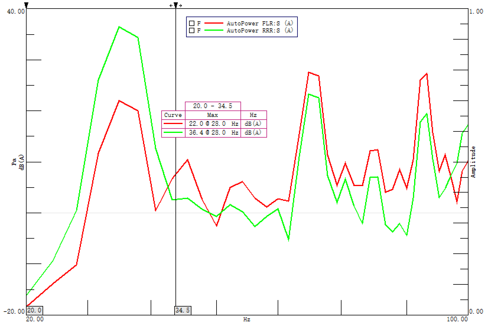
Figure 1: Cabin Noise Spectrum – Front and Rear Seats
A quick perturbation test was carried out targeting the rear-cabin ear pressure issue. After disconnecting the No.5 exhaust hanger, the 28 Hz noise peak at the rear cabin dropped from 36.4 dB(A) to 23.5 dB(A), showing remarkable improvement in rear cabin noise. The measured spectrum is shown in the figure below.
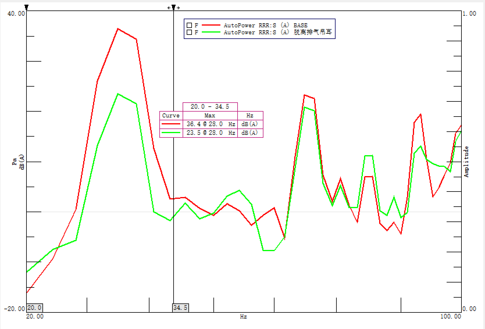
Figure 2: Comparison of Rear Cabin Noise Spectrum with No.5 Exhaust Hanger Disconnected
二
Problem Analysis and Optimization
The test results indicate that the rear cabin ear pressure issue originates from the No.5 exhaust hanger. Optimization work will be carried out focusing on frame modal analysis, exhaust system modal characteristics, dynamic stiffness of the No.5 hanger and the layout of exhaust hangers.
2.1 Modal Coupling
The 2nd-order frequency of this pickup engine at idle is 28 Hz, meaning 25 Hz to 31 Hz is the coupling resonance range. CAE analysis shows:
● There is no exhaust system mode within this range;
● The first bending mode of the frame is 26.9 Hz, very close to the idle 28 Hz;
● The No.5 hanger is arranged at the rear end of the frame, at the anti-node position of the first bending mode.
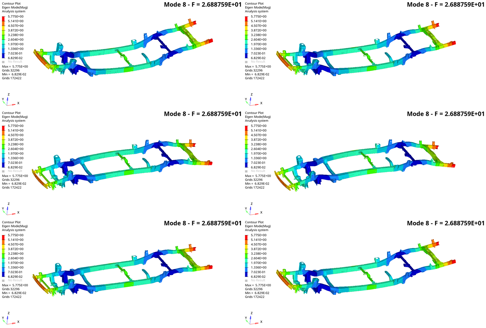
Figure 3: First Bending Mode of the Frame
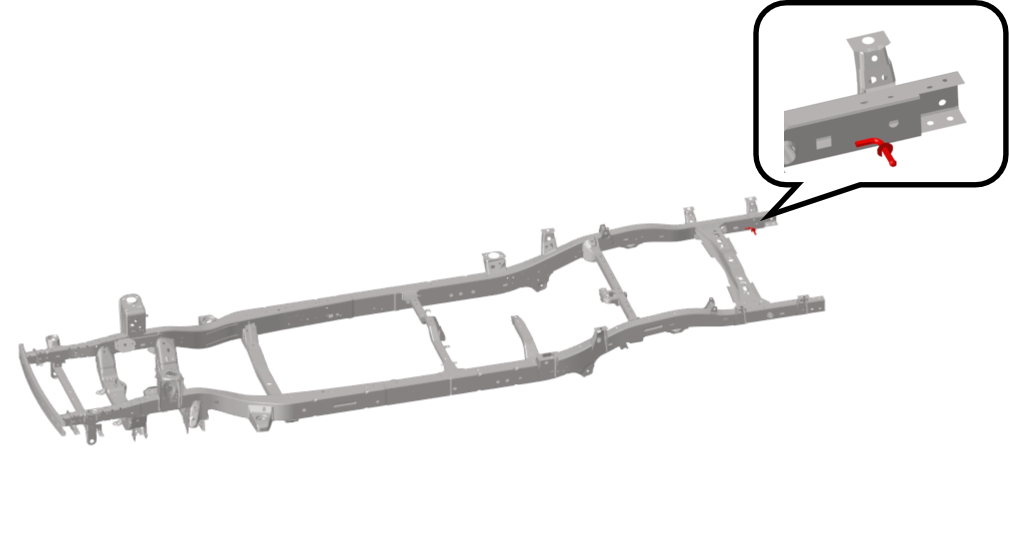
Figure 4: Location of No.5 Exhaust Hanger
A modal node line refers to the geometric trace where the vibration displacement amplitude remains zero and stationary during vibration at a specific natural mode. Regions on both sides of the node line vibrate in opposite phases. It serves as a critical boundary feature for stiffness contribution and vibration energy distribution in the mode shape. In NVH analysis and vibration control, the node line location directly identifies sensitive zones for structural stiffness optimization. Reinforcing constraints at node lines can effectively alter the structural natural frequency. Meanwhile, placing excitation sources or response-sensitive points near node lines can greatly reduce vibration transmission and resonance amplification, providing key engineering references for idle vibration and structural resonance issues. From the mode shape plot, the node line of the frame’s first bending mode lies at the 6th cross-member. NVH optimization suggestion: relocate the No.5 exhaust hanger close to the 6th cross-member.
2.2 Hanger Vibration Isolation
Dynamic stiffness refers to the dynamic force required per unit displacement under dynamic excitation. It directly governs the vibration transmissibility to the vehicle body and serves as a key indicator for resolving ear pressure, booming and shudder issues. The dynamic stiffness analysis of the No.5 exhaust hanger shows that its dynamic stiffness at 27 Hz is 99.5 N/mm, failing to meet the target requirement of 480 N/mm (the rubber dynamic stiffness of the hanger is 48 N/mm). After relocating the hanger to the 6th cross-member, the dynamic stiffness at the problem frequency rises from 99.5 N/mm to 491.9 N/mm.
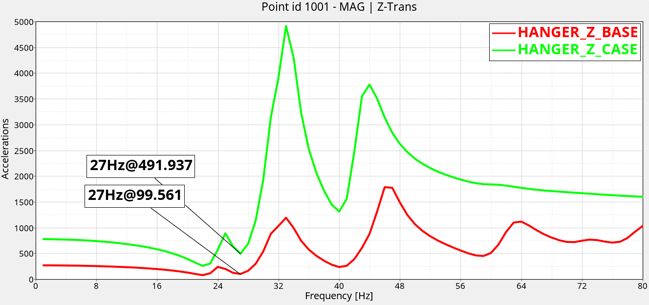
Figure 5: Dynamic Stiffness Comparison of No.5 Exhaust Hanger
2.3 Vehicle Prototype Verification
The optimization scheme derived from simulation was validated on the prototype vehicle by relocating the No.5 exhaust hanger of the exhaust system to the 6th cross-member. The 28 Hz noise peak in the rear cabin decreased from 36.4 dB(A) to 22.0 dB(A), and the rear cabin ear pressure sensation was eliminated.
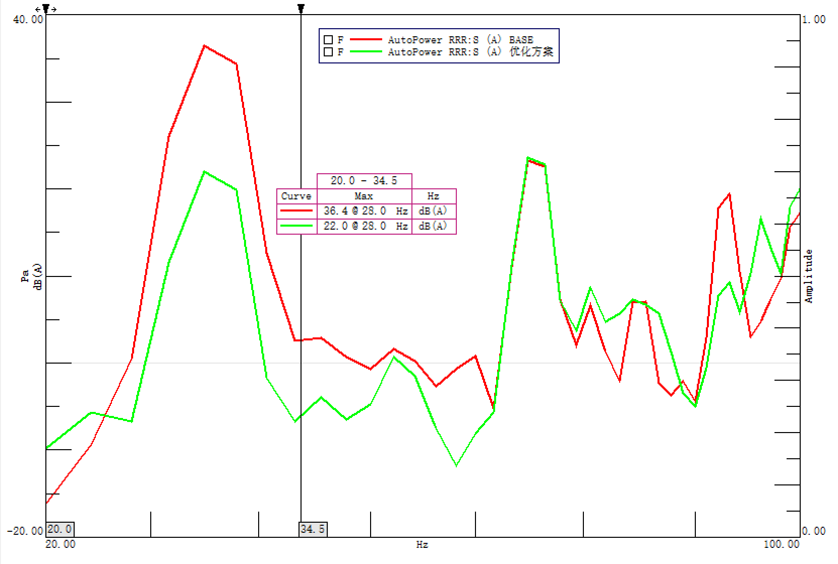
Figure 6: Noise Spectrum Comparison of No.5 Exhaust Hanger for Prototype Scheme
三
Extended Reflections
Components with excitation sources in a vehicle (e.g., compressors, cooling fans, intake systems) inevitably suffer modal coupling with other parts or systems. At the data development stage, CAE-based structural optimization can be adopted to achieve modal decoupling between excitation sources and various systems. If modal coupling still exists during prototype vehicle tuning, the connecting structures of all excitation sources should be preferentially placed at modal node lines, avoiding high-amplitude and high-displacement sensitive zones such as anti-nodes to prevent the risk of amplified vibration coupling. This approach effectively reduces vibration transmission to the vehicle body, avoids NVH issues including idle shudder, cabin ear pressure and structural booming, and improves overall ride comfort and vehicle quality.

回到顶部






 请留下联系方式,我们将尽快与您联系!