Aiming at the "horse-riding" low-frequency vibration of the cab of a heavy-duty truck under the constant speed condition of 40–50 km/h, vehicle vibration isolation, rigid body modal testing and mount excitation displacement tests were carried out to analyze the vibration excitation sources, transmission paths and modal coupling mechanism. A 6-DOF (six-degree-of-freedom) dynamic model of the cab was established based on inertial parameters and component performance parameters. ADAMS was adopted to analyze rigid body modes and decoupling rates. Combined with DOE and Isight, multi-objective optimization of the cab suspension system was realized. Finally, suspension stiffness and damping matching were completed and verified through vehicle tuning. The results show that the "horse-riding" phenomenon disappears at 40–50 km/h after tuning, and the cab vibration peaks under various working conditions are greatly reduced, approaching the level of benchmark vehicles.
一
Problem Description
In the China VI cab development project for a heavy-duty truck, multi-objective simulation optimization of rigid body mode distribution and decoupling was required for the 2.5 m low-hood raised-roof cab suspension system to improve the vehicle-level NVH performance. The vehicle adopts a fully-floating cab with air spring mounts. Its engine delivers a maximum power of 347 kW. The FAW J7 (370 kW) equipped with air spring mounts of the same class was selected as the benchmark vehicle for performance comparison.
Vehicle evaluation revealed that the baseline vehicle exhibited noticeable low-frequency "horse-riding" vibration of the cab under the cruising condition of 40–50 km/h, which was subjectively unacceptable. Objective measurements were performed using the ATOM Analyzer. The test results show that the vibration at the seat rail exceeds 40 mg near 50 km/h. The cab vibration across constant-speed conditions from 40 to 80 km/h is generally higher than that of the benchmark vehicle in the 2–20 Hz frequency band, with dominant frequency components around 2.75 Hz, 3.25 Hz, 3.75 Hz and 4 Hz, as shown in Figure 1. The problematic frequencies highly coincide with the first-order tire excitation frequency (3.25–4 Hz corresponding to 40–50 km/h). It is preliminarily concluded that the vibration is related to road excitation.
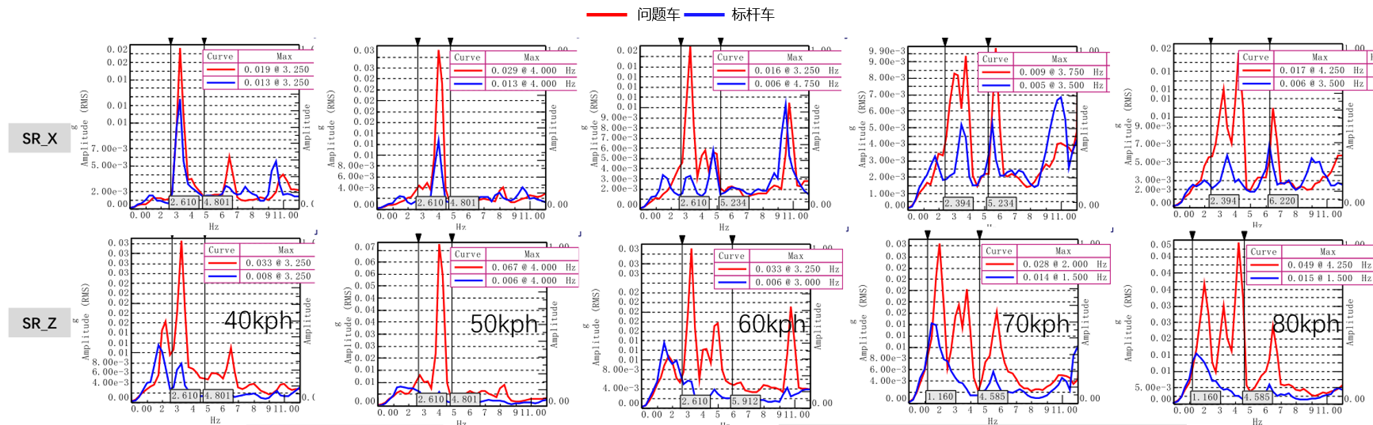
Figure 1 Comparison of Cab Vibration Spectra under Different Vehicle Speed Conditions
二
Cause Analysis
2.1 Excitation Source Analysis
Under constant-speed driving conditions, the in-cab vibration excitation sources mainly originate from the powertrain and wheel hub vibrations. Vibration may be attenuated or amplified along the transfer path; it is more likely to be transmitted and amplified when modal coupling exists in structural components. Vibration is transmitted to the cab via a three-stage path: wheel → frame → body → steering wheel/seat, as shown in Figure 2. The vibration on the frame side transfers into the cab through air spring dampers. Comparative tests indicate that the wheel hub vibration of the baseline vehicle is generally higher than that of the benchmark vehicle within the 20 Hz frequency range, which means the energy of road excitation is relatively high.
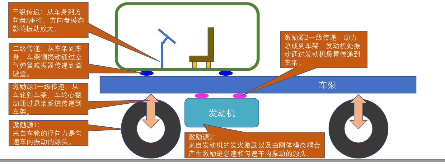
Figure 2 Excitation Sources and Three-Stage Transfer Paths of Cab Vibration
2.2 Transfer Path and Mount Vibration Isolation Analysis
The cab suspension is a key element through which road excitation is transmitted to the cab. A comparison of the vibration on the active and passive sides of the suspensions of the two vehicles shows that the benchmark vehicle's suspension begins to isolate vibration above 3 Hz and achieves good isolation effect. In contrast, the baseline vehicle's suspension starts isolating vibration around 6 Hz, and its isolation performance is noticeably inferior to that of the benchmark vehicle, allowing a large amount of low-frequency vibration in the 3–6 Hz band to be transmitted to the cab.
Meanwhile, under all constant-speed conditions, the suspension excitation displacement of the baseline vehicle is greater than that of the benchmark vehicle (at 80 km/h: ±4.0 mm vs. ±2.5 mm). The larger the displacement, the greater the in-cab vibration, which indicates that the vibration isolation capability of the baseline vehicle's suspension is insufficient.
2.3 Cab Rigid Body Mode Analysis
The rigid body modal test of the cabs of both vehicles was carried out using the hammer excitation method (8 sensors arranged around the perimeter, with an onboard load of 300 kg). The first six rigid body modal frequencies of the baseline vehicle are 2.0, 3.2, 3.9, 4.4, 4.9 and 6.4 Hz. The 2nd, 3rd and 4th modes have close frequency values, and their mode shapes all show a trend of vertical motion, resulting in obvious vertical modal coupling. Among them, the 3.2 Hz mode is close to the problematic in-cab frequency of 3.25 Hz, as shown in Figure 3. The first six modal frequencies of the benchmark vehicle are 1.7, 2.6, 3.6, 4.8, 6.8 and 7.3 Hz. The intervals between the 2nd, 3rd and 4th modes are approximately 1 Hz, indicating a significantly better decoupling state compared with the baseline vehicle.
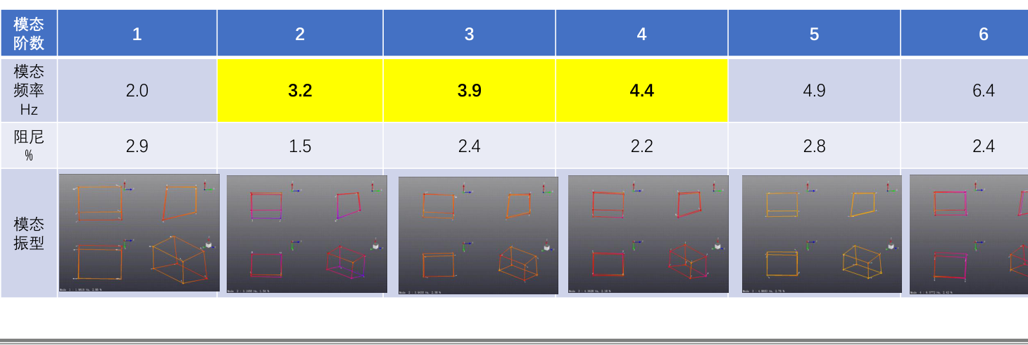
Figure 3 Test Results of the First Six Rigid Body Modes of the Baseline Vehicle Cab
2.4 Mechanism Identification of the Problem
Based on the above analysis, the low-frequency vibration mechanism of the baseline vehicle at 40–50 km/h is preliminarily determined as follows: the tire rotational frequency excitation (3.25–4 Hz) falls within the cab rigid body modal frequency band. Coupled with insufficient vibration isolation of the mounts and vertical modal coupling among the 2nd, 3rd and 4th modes, large low-frequency responses are generated in the cab. Accordingly, the optimization target for mount matching is defined: reduce the 3.2 Hz vertical mode to approximately 2.6 Hz, while ensuring the frequency spacing and decoupling rate of each mode.
三
Simulation Analysis
3.1 Cab Dynamic Modeling
Under steady-state operating conditions such as idling and constant-speed cruising, the cab is in a "suspended" state and is mainly constrained by the elastic boundaries of air spring mounts and limiting rubber bushings. During modeling, the stiffness of the front mount assembly is taken as the sum of the Z-direction stiffness of the front airbag and the X-direction stiffness of the limiting bushing. The stiffness of the rear mount assembly is defined as the sum of the Z-direction stiffness and damping of the rear airbag and the Y-direction stiffness of the limiting bushing. The inertia parameters of the cab were measured via the moment of inertia separation method. Combined with mount hard points and component performance parameters, a six-degree-of-freedom dynamic model of the cab was built in ADAMS.
3.2 Rigid Body Mode and Decoupling Rate Analysis
Modal analysis was performed using the ADAMS Vibration module. The problematic frequency of 3.2 Hz was reproduced in simulation. The vertical decoupling rate reaches 99.81%, while the decoupling rates in the X-direction (61.1%), Y-direction (63.07%), roll (46.5%), pitch (58.1%) and yaw (48.36%) directions are relatively low. This verifies the model’s capability to reproduce the modal coupling issue, as shown in Figure 4.

Figure 4 Analysis Results of Cab Rigid Body Modes and Decoupling Rates (ADAMS)
3.3 Multi-objective Optimization and Robustness Analysis
Taking the decoupling rate as the objective function, the ADAMS Insight module was used to evaluate the DOE design of mount stiffness and installation positions. The maximum achievable decoupling rates in all directions were obtained (vertical: 99.99%, yaw: 76.6%, etc.). Through sensitivity analysis, the factors with the greatest influence on the vertical decoupling rate were identified, providing guidance for vehicle tuning.
Considering manufacturing tolerances in actual mount stiffness and mounting points, Isight was further employed for robustness analysis and optimization. The results show that, before optimization, the sigma value of the vertical decoupling rate was only 0.647 and the sigma value of the FreqZ mode was only 1.964. After optimization, these values were improved to 4.958 and 2.9 respectively, indicating a significant enhancement in robustness, as shown in Figure 5. After adjusting the stiffness parameters, the first four cab modes were concentrated within 3 Hz, and the vertical decoupling rate reached 93%. Based on the theoretical mathematical model, a "Mountsim" program for rigid body mode decoupling calculation and optimization of the mount system was also developed.
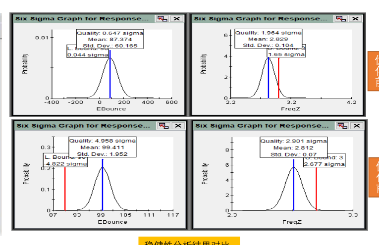
Figure 5 Comparison of Six Sigma Analysis Results Before and After Robustness Optimization (Isight)
四
Vehicle Optimization Verification
4.1 Real-Vehicle Confirmation of Root Cause
At the vehicle tuning stage, the problem mechanism was verified first. The cab was excited by impact hammer on the complete vehicle, and the frequency response exhibited modal frequencies of 2, 2.99, 4.2, 6.28 and 8.53 Hz. Among them, the 4.2 Hz component corresponded to the 50 km/h operating condition. After lifting the front end of the frame to separate the front wheels from the ground and eliminate the influence of sprung modes, the 4.2 Hz characteristic disappeared, ruling out the cab rigid body mode as the source.
Full-vehicle modal tests under full load identified a 3.82 Hz global vehicle mode, generated by frame pitch motion excited by the vertical rigid body mode of the fully loaded trailer. ABA verification showed that the low-frequency shudder at 40–50 km/h and the 4.2 Hz characteristic vanished when the fully loaded trailer was removed, and reappeared once the trailer was reattached, as shown in Figure 6. The bounce test measured the sprung natural frequency of the rear drive axle under full load at approximately 3.4 Hz. It is confirmed that the 3.82 Hz component originates from the vertical rigid body mode of the mass-spring system consisting of drive axle leaf springs, trailer leaf springs and the mass of the fully loaded trailer.
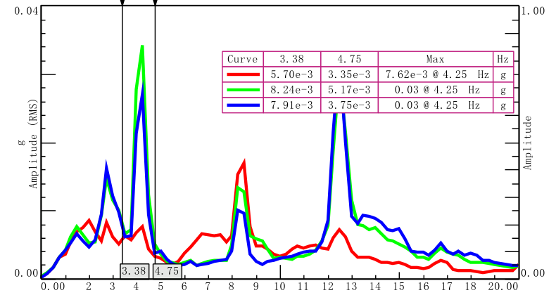
Figure 6 ABA Verification Results with the Fully Loaded Trailer Removed
To resolve the issue at its source, it is necessary to adjust the leaf springs of the rear drive axle (the theoretical sprung natural frequency under full load ≤2.85 Hz) or the trailer leaf springs. However, this involves chassis modification with long lead time and high risks. Given the heavy mass of the fully loaded trailer and the large inertial force once its mode is excited, an engineering solution is adopted to suppress the response by optimizing cab mount parameters and matching damping and stiffness via real-vehicle tuning.
4.2 Mount Damping and Stiffness Matching
Three states were compared for mount damping matching: standard damping, increased damping in the low-speed range, and zero damping. Increased damping aggravated the low-frequency shudder at 50 km/h and was unacceptable. The zero-damping scheme showed no obvious low-frequency shudder but generated prominent mount impact noise on undulating roads, which was also unacceptable. The X-direction vibration at the seat rail was reduced from 18 mg to 4 mg. Stiffness matching was verified through different pressure combinations of air mounts with zero damping. When the pressure of both front and rear airbags was reduced to 0.25 MPa, obvious cab shudder occurred, which was unacceptable. After comprehensive trade-off, the parameters were finalized: front air mount stiffness of 16 and rear air mount stiffness of 10, equipped with rear hydraulic lock bushings and front comfort bushings.
4.3 Optimization Effect Verification
After parameter finalization, cab vibration was remeasured under various constant-speed conditions. The "horse-riding" phenomenon at 40–50 km/h disappeared, and no obvious vibration issues were observed at all vehicle speeds. The objective vibration peak values were greatly reduced compared with the original state and were close to those of the benchmark vehicle. (For example, at 40 km/h, X-direction vibration decreased from 19 mg to 7 mg; at 50 km/h, X-direction vibration dropped from 29 mg to 10 mg and Z-direction vibration from 67 mg to 17 mg), as shown in Figure 7 and Table 1.
The isolation rate of the front mounts in the primary directions generally exceeds 70%, while that of the rear mounts reaches over 60%. The weighted acceleration at the passive side of the mounts at 70 km/h and 80 km/h is less than 0.59 m/s² and 0.63 m/s² respectively, meeting the development targets.
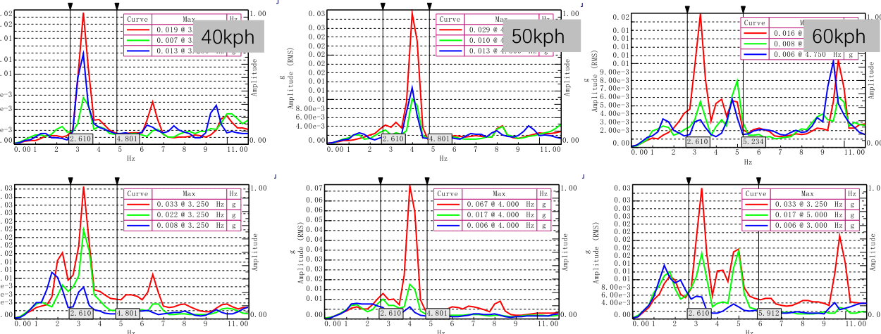
Figure 7 Comparison of Cab Vibration Peaks Before and After Tuning
Table 1 Comparison of Cab Vibration Peaks at Different Vehicle Speeds Before and After Tuning
(Unit: mg)
Speed Condition | Direction | Original | Tuned | Benchmark |
40 km/h | X | 19 | 7 | 13 |
Z | 32 | 22 | 8 | |
50 km/h | X | 29 | 10 | 13 |
Z | 67 | 17 | 6 | |
60 km/h | X | 16 | 8 | 6 |
Z | 33 | 17 | 6 | |
70 km/h | X | 10 | 4 | 5 |
Z | 28 | 15 | 14 | |
80 km/h | X | 17 | 13 | 6 |
Z | 49 | 18 | 15 |
五
Conclusion
Through the closed-loop workflow of "test analysis — simulation optimization — real-vehicle verification", it is confirmed that the low-frequency cab vibration of the base vehicle at 40–50 km/h mainly originates from the vertical rigid body mode (3.82 Hz) of the mass-spring system of the fully loaded trailer. This excites frame pitch motion, which is amplified via mounts with insufficient vibration isolation capacity and coupled with the cab vertical rigid body mode. Superimposed with tire rotational frequency excitation, it generates the "horse-riding" vibration phenomenon.
The mount multi-objective optimization method targeting rigid body mode frequency distribution, decoupling rate and robustness can effectively guide mount parameter matching. The developed program for rigid body mode decoupling calculation and optimization of the mount system has engineering promotion value.
After the mount stiffness and damping parameters were finalized through real-vehicle tuning, the "horse-riding" phenomenon at 40–50 km/h disappeared. Cab vibration under all operating conditions was greatly reduced and approached the level of the benchmark vehicle. This validates the feasibility of combining simulation optimization with real-vehicle parameter matching.
During the early-stage development of heavy-duty trucks, coupling between cab rigid body modes and excitation frequencies shall be avoided. Sufficient frequency separation and acceptable decoupling rates for each mode shall be guaranteed. Besides, the influence of coupled modes from fully loaded trailers on cab vibration should be comprehensively considered.

回到顶部






 请留下联系方式,我们将尽快与您联系!